Tekniset tiedot
Notes
General
Note Repeated hard short circuits can reduce the melting integral of the integrated backup fuse.
Product properties
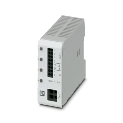
Type DIN rail module, one-piece
Product type Device circuit breakers
Product family CBMC
Number of positions 1
No. of channels 4
Insulation characteristics
Protection class III
Pollution degree 2
Electrical properties
No. of channels 4
General
Operating voltage 18 V DC … 30 V DC
Rated voltage 24 V DC
Rated current IN max. 40 A DC (IN+)
max. 40 A DC (per terminal position when bridging additional devices via IN+)
Rated current IN 1 / 2 / 3 / 4 / 5 / 6 / 7 / 8 / 9 / 10 A DC (adjustable per output channel)
Rated current (pre-adjusted) 4 A
Rated surge voltage 0.5 kV
Tripping method E (electronic)
Feedback resistance max. 35 V DC
Required backup fuse Only required if Imax of the power supply > the short-circuit switching capacity. Integrated failsafe element.
Short-circuit switching capacity 300 A
Dielectric strength max. 35 V DC (Load circuit)
Fuse electronic
Efficiency > 99 %
Closed circuit current I0 typ. 25 mA
Power dissipation typ. 0.6 W (No-load operation)
< 9 W (Nominal operation)
Module initialization time 1.6 s
Waiting time after switch off of a channel 5 s (at overload / short circuit)
Measuring tolerance I ± 15 %
Temperature derating 24 A DC (at 60 °C)
28 A DC (at 54 °C)
32 A DC (at 47 °C)
36 A DC (at 41 °C)
40 A DC (at 35 °C)
MTBF (IEC 61709, SN 29500) 8403361 h (at 25 °C with 21 % load)
3067484 h (at 40°C with 34.25% load)
534188 h (at 35 °C with 100 % load)
Fail-safe element 15 A DC (per output channel)
Load circuit
Shutdown time ≤ 10 ms (for short circuit > 2.0 x IN)
1 s (1.2 … 2.0 x IN)
Undervoltage switch-off ≤ 17.8 V DC (active)
≥ 18.8 V DC (inactive)
Overvoltage switch-off ≥ 30.5 V DC (active)
≤ 29.5 V DC (inactive)
Max. capacitive load 45000 µF (Depending on the current setting and the short-circuit current available)
Indicator/remote signaling
Connection name Remote indication circuit
Switching function N/O contact
Operating voltage 0 V DC … 30 V DC
Operating current 100 mA DC
Connection data
Cross section AWG (converted acc. to IEC)
Main circuit IN+
Connection method Push-in connection
Stripping length 15 mm
Conductor cross section rigid 0.2 mm² … 10 mm²
Conductor cross section AWG 24 … 8
Conductor cross section, flexible, with ferrule, with plastic sleeve 0.25 mm² … 4 mm²
Conductor cross section flexible, with ferrule without plastic sleeve 0.25 mm² … 6 mm²
Main circuit IN-
Connection method Push-in connection
Stripping length 10 mm
Conductor cross section rigid 0.2 mm² … 2.5 mm²
Conductor cross section AWG 24 … 12
Conductor cross section, flexible, with ferrule, with plastic sleeve 0.25 mm² … 1.5 mm²
Conductor cross section flexible, with ferrule without plastic sleeve 0.25 mm² … 2.5 mm²
Main circuit OUT
Connection method Push-in connection
Stripping length 10 mm
Conductor cross section rigid 0.2 mm² … 2.5 mm²
Conductor cross section AWG 24 … 12
Conductor cross section, flexible, with ferrule, with plastic sleeve 0.25 mm² … 1.5 mm²
Conductor cross section flexible, with ferrule without plastic sleeve 0.25 mm² … 2.5 mm²
Remote indication circuit
Stripping length 10 mm
Conductor cross section rigid 0.2 mm² … 2.5 mm²
Conductor cross section AWG 24 … 12
Conductor cross section, flexible, with ferrule, with plastic sleeve 0.25 mm² … 1.5 mm²
Conductor cross section flexible, with ferrule without plastic sleeve 0.25 mm² … 2.5 mm²
Signaling
Channel LED off off (Channel switched off)
Channel LED yellow lit (Channel switched on, channel load > 80% )
flashing (Programming mode active)
Channel LED green lit (Channel switched on)
Channel LED red lit (Channel switched off, over- or undervoltage active)
ON temporarily (Channel switched off, 5 s cool-down phase, overload or short-circuit release)
flashing (Channel switched off, ready to be switched back on, overload or short-circuit release)
two flashes (Channel switched off, device total current limit 40 A exceeded)
Dimensions
Width 36 mm
Height 90 mm
Depth 98 mm (incl. DIN rail 7.5 mm)
Material specifications
Material PC
PA 6.6
PA 6.3T
POM
Flammability rating according to UL 94 V-0
Environmental and real-life conditions
Ambient conditions
Degree of protection IP20
Ambient temperature (operation) -25 °C … 60 °C
Ambient temperature (storage/transport) -40 °C … 70 °C
Altitude ≤ 3000 m up to 52 °C (amsl)
≤ 4000 m up to 46 °C (amsl)
Humidity test 96 h, 95 % RH, 40 °C
Shock (operation) 30g (IEC 60068-2-27, Test Ea)
Vibration (operation) 10 Hz … 57.6 Hz (Amplitude ±0.35 mm; in accordance with IEC 60068-2-6, Test Fc)
57.6 Hz … 150 Hz (Acceleration 5g; in accordance with IEC 60068-2-6, Test Fc)
Approvals
UL approval
Identification UL/C-UL Listed UL 508
UL Recognized UL 2367
Standards and regulations
Standards/specifications EN 61000-6-2
Note EMC – Immunity for industrial areas
Standards/specifications EN 61000-6-3
Note EMC – Emission for residential, business and commercial properties and small operations
Standards/specifications EN 60068-2-6
Note Environmental influences – Vibrations (sinusoidal)
Standards/specifications EN 60068-2-27
Note Environmental influences – Shocks
Standards/specifications EN 60068-2-78
Note Environmental influences – Moisture and heat, constant
Standards/specifications EN 50178
Note Equipping power installations with electronic equipment
Mounting
Mounting type DIN rail: 35 mm
Muut tiedot
Tuotenumero 2906032
Pakkausyksikkö 1 Kappaletta
Tuoteavain CLA152
Tuotekoodi CLA152
GTIN 4055626149356
Paino kappaletta kohti (sis. pakkauksen) 140,2 g
Paino kappaletta kohti (ilman pakkausta) 133,94 g
Tullitariffinumero 85362010
Alkuperämaa DE
Tutustu myös