Tekniset tiedot
Product properties
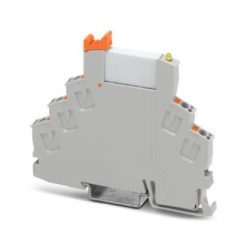
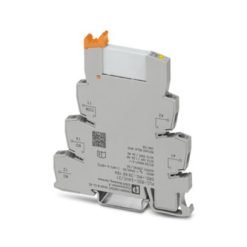
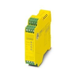
Product type Safety relays
Product family PSRmini
Application Emergency stop
Safety door
Solenoid switch
Transponder
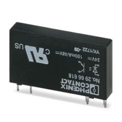
Relay type Electromechanical relay with force-guided contacts in accordance with IEC/EN 61810-3
Times
Typical response time < 175 ms
Typical release time < 20 ms (when controlled via A1 or S12 and S22.)
Recovery time < 500 ms
Electrical properties
Maximum power dissipation for nominal condition 3 W ()
Nominal operating mode 100% operating factor
Air clearances and creepage distances between the power circuits
Rated insulation voltage 250 V AC
250 V AC
Rated surge voltage/insulation Safe isolation, reinforced insulation 6 kV between input circuit and enabling current path
Basic insulation 4 kV between all current paths and housing
Supply
Designation A1/A2
Rated control circuit supply voltage US 20.4 V DC … 26.4 V DC
Rated control circuit supply voltage US 24 V DC -15 % / +10 %
Rated control supply current IS typ. 42 mA
Power consumption at US typ. 1 W
Inrush current 4.5 A (Δt < 120 µs at Us)
Filter time 1 ms (at A1 in the event of voltage dips at Us)
Protective circuit Surge protection; Suppressor diode
Protection against polarity reversal for rated control circuit supply voltage
Input data
Digital: Sensor circuit (S11, S12, S22)
Description of the input safety-related sensor inputs
Input voltage range ”0” signal 0 V DC … 5 V DC (for safe Off; at S12)
Input current range ”0” signal 0 mA … 2 mA (for safe Off; at S12)
Inrush current < 20 mA (with Us/Ix to S12)
< 5 mA (with Us/Ix to S22)
> -15 mA (with Us/Ix to S22/0V)
Filter time max. 1.5 ms (at S12, S22; test pulse width)
min. 7.5 ms (at S12, S22; test pulse rate)
Test pulse rate = 5 x Test pulse width
Max. permissible overall conductor resistance 150 Ω
Current consumption < 5 mA (with Us/Ix to S12)
< 5 mA (with Us/Ix to S22)
> -5 mA (with Us/Ix to S22/0V)
Digital: Start circuit (S34)
Description of the input non-safety-related
Number of inputs 1
Input voltage range ”1” signal 20.4 V DC … 26.4 V DC
Inrush current < 10 mA
Max. permissible overall conductor resistance 150 Ω
Protective circuit Suppressor diode
Current consumption < 10 mA
Output data
Relay: Enabling current path (13/14)
Output description safety-related N/O contacts
Number of outputs 1 (undelayed)
Contact switching type 1 enabling current path
Contact material AgSnO2
Switching voltage min. 12 V AC/DC
max. 250 V AC/DC (Observe the load curve)
Switching capacity min. 60 mW
Inrush current min. 3 mA
max. 6 A
Limiting continuous current 6 A (observe derating)
Sq. Total current 36 A2 (observe derating)
Switching frequency max. 0.5 Hz
Mechanical service life 10x 106 cycles
Output fuse 6 A gL/gG (N/O contact)
4 A gL/gG (for low-demand applications)
Connection data
Connection technology
pluggable no
Conductor connection
Connection method Screw connection
Conductor cross section rigid 0.2 mm² … 2.5 mm²
Conductor cross section flexible 0.2 mm² … 2.5 mm²
Conductor cross-section AWG 24 … 12
Stripping length 12 mm
Screw thread M3
Signaling
Status display 2 x green LEDs
Operating voltage display 1 x green LED
Dimensions
Width 6.8 mm
Height 93.1 mm
Depth 102.5 mm
Material specifications
Color (Housing) yellow (RAL 1018)
Housing material PBT
Characteristics
Safety data
Stop category 0
Safety data: EN ISO 13849
Category 4
Performance level (PL) e (4 A DC13; 5 A AC15; 8760 switching cycles/year)
Safety data: IEC 61508 – High demand
Safety Integrity Level (SIL) 3
Safety data: IEC 61508 – Low demand
Safety Integrity Level (SIL) 3
Safety data: EN IEC 62061
Safety Integrity Level (SIL) 3
Environmental and real-life conditions
Ambient conditions
Degree of protection IP20
Min. degree of protection of inst. location IP54
Ambient temperature (operation) -40 °C … 60 °C (observe derating)
Ambient temperature (storage/transport) -40 °C … 85 °C
Maximum altitude ≤ 2000 m (Above sea level)
Max. permissible humidity (storage/transport) 75 % (on average, 85% infrequently, non-condensing)
Max. permissible relative humidity (operation) 75 % (on average, 85% infrequently, non-condensing)
Shock 15g
Vibration (operation) 10 Hz … 150 Hz, 2g
Approvals
CE
Certificate CE-compliant
Standards and regulations
Air clearances and creepage distances between the power circuits
Standards/regulations EN 60947-1
Mounting
Mounting type DIN rail mounting
Mounting position vertical or horizontal
Connection method Screw connection
Muut tiedot
Tuotenumero 2904953
Pakkausyksikkö 1 Kappaletta
Tuoteavain DNA171
Tuotekoodi DNA171
GTIN 4046356905015
Paino kappaletta kohti (sis. pakkauksen) 87,4 g
Paino kappaletta kohti (ilman pakkausta) 69 g
Tullitariffinumero 85371098
Alkuperämaa DE