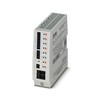
Electronic circuit breaker

Multi-channel, electronic device circuit breaker with active current limitation for protecting eight loads at 24 V DC in the event of overload and short circuit. With nominal current assistant and electronic locking of the set nominal currents. For installation on DIN rails.
Tekniset tiedot
Product properties
Type DIN rail module, one-piece
Product type Device circuit breakers
Product family CBM
Number of positions 1
No. of channels 8
Insulation characteristics
Protection class III
Pollution degree 2
Electrical properties
No. of channels 8
General
Operating voltage 18 V DC … 30 V DC
Rated voltage 24 V DC
Rated current IN max. 80 A DC (for double supply IN+ with at least 2 x 6 mm²)
max. 70 A DC (for UL 2367)
Rated current IN 0.5 / 1 / 2 / 4 / 6 / 10 A DC (adjustable per output channel)
Rated current (pre-adjusted) 0.5 A
Rated surge voltage 0.5 kV
Tripping method E (electronic)
Feedback resistance max. 35 V DC
Required backup fuse Only required if Imax of the power supply > the short-circuit switching capacity. Integrated failsafe element.
Short-circuit switching capacity 300 A
Dielectric strength max. 30 V DC (Load circuit)
Active current limitation typ. 1.5 x IN (2 – 10 A)
Fuse electronic
Efficiency > 99 %
Closed circuit current I0 typ. 50 mA
Power dissipation 1.2 W (No-load operation)
17.2 W (Nominal operation)
Module initialization time 3.3 s
Waiting time after switch off of a channel 10 s (at overload / short circuit)
Measuring tolerance I typ. 40 % (0.5 A … 1 A)
typ. 10 % (2 – 10 A)
Temperature derating 40 A DC (at 70°C (65°C for UL 2367))
50 A DC (at 60 °C)
60 A DC (at 50 °C)
70 A DC (at 40 °C)
80 A DC (at 40 °C)
70 A DC (at 40°C for UL 2367)
MTBF (IEC 61709, SN 29500) 1304293 h (at 25 °C)
858501 h (at 40 °C)
440048 h (at 60 °C)
Fail-safe element 15 A DC (per output channel)
Load circuit
Shutdown time 0.02 s (> 1.3 x IN)
30 s (1.1 … 1.3 x IN)
Undervoltage switch-off ≤ 17.8 V DC (active)
≥ 19 V DC (inactive)
Overvoltage switch-off ≥ 30.5 V DC (active)
≤ 29.5 V DC (inactive)
Max. capacitive load 75000 µF
Reset
Input voltage range 7 V DC … 30 V DC (Reset with falling edge)
Current consumption typ. 0.4 mA (at 24 V DC)
Pulse length ≥ 50 ms (High signal)
≥ 50 ms (Low signal)
Voltage < 5 V DC (Low signal)
> 8 V DC (High signal)
Status output
Output voltage 24 V DC
Output current max. 20 mA (when I > 80% at at least one channel)
Indicator/remote signaling
Connection name Remote indication circuit
Switching function N/O contact
Operating voltage 0 V DC … 30 V DC
Operating current 1 mA DC … 100 mA DC
Connection data
Cross section AWG (converted acc. to IEC)
Main circuit IN+
Connection method Push-in connection
Stripping length 18 mm
Conductor cross section rigid 0.75 mm² … 16 mm²
Conductor cross section AWG 20 … 4
Conductor cross section, flexible, with ferrule, with plastic sleeve 0.75 mm² … 10 mm²
Conductor cross section flexible, with ferrule without plastic sleeve 0.75 mm² … 16 mm²
Main circuit IN-
Connection method Push-in connection
Stripping length 10 mm
Conductor cross section rigid 0.2 mm² … 2.5 mm²
Conductor cross section AWG 24 … 12
Conductor cross section, flexible, with ferrule, with plastic sleeve 0.25 mm² … 1.5 mm²
Conductor cross section flexible, with ferrule without plastic sleeve 0.25 mm² … 2.5 mm²
Main circuit OUT
Connection method Push-in connection
Stripping length 10 mm
Conductor cross section rigid 0.2 mm² … 2.5 mm²
Conductor cross section AWG 24 … 12
Conductor cross section, flexible, with ferrule, with plastic sleeve 0.25 mm² … 1.5 mm²
Conductor cross section flexible, with ferrule without plastic sleeve 0.25 mm² … 2.5 mm²
Remote indication circuit
Stripping length 10 mm
Conductor cross section rigid 0.2 mm² … 2.5 mm²
Conductor cross section AWG 24 … 12
Conductor cross section, flexible, with ferrule, with plastic sleeve 0.25 mm² … 1.5 mm²
Conductor cross section flexible, with ferrule without plastic sleeve 0.25 mm² … 2.5 mm²
Signaling
DC OK LED off off (No supply voltage)
DC OK LED yellow lit (Undervoltage active, voltage ≤ 17.8 V, active channels switched off and channel LEDs are lit red)
flashing (Undervoltage switch-off inactive, device was in undervoltage switch-off)
DC OK LED green lit (Operating voltage in nominal range 18 … 30 V)
DC OK LED red lit (Overvoltage switch-off active, voltage ≥ 30.5 V, channels switched off and channel LEDs are lit red)
flashing (Overvoltage switch-off inactive, device was in overvoltage shutdown)
Channel LED off off (Channel switched off)
Channel LED yellow lit (Channel switched on, channel load > 80% )
Channel LED yellow-green flashing (Channel switched on, nominal current assistant active)
Channel LED green lit (Channel switched on)
flashing (Channel switched on, programming mode active)
Channel LED red lit (Channel switched off, over- or undervoltage active)
ON temporarily (Channel switched off, 10 s cool-down phase, overload or short-circuit release)
flashing (Channel switched off, ready to be switched back on, overload or short-circuit release)
Channel LED red-yellow flashing (Channel switched on, overload mode, capacity approximately 110 … 130% , shutdown after 30 s)
Channel LED red-green flashing (Channel switched off, programming mode active, current adjustment after overload or short-circuit release)
Dimensions
Width 41 mm
Height 130 mm
Depth 121 mm (incl. DIN rail 7.5 mm)
Material specifications
Material PC
PA 6.6
PC
PBT-FR17
POM
Flammability rating according to UL 94 V-0
Environmental and real-life conditions
Ambient conditions
Degree of protection IP20
Ambient temperature (operation) -25 °C … 70 °C (Startup at -40 C type-tested)
-25 °C … 65 °C (for UL 2367)
Ambient temperature (storage/transport) -40 °C … 80 °C
Altitude ≤ 6000 m (amsl)
Humidity test 240 h, 95 % RH, 40 °C
Shock (operation) 30g (IEC 60068-2-27, Test Ea)
Vibration (operation) 5 Hz … 24.9 Hz (Amplitude ±1.6 mm; in accordance with IEC 60068-2-6, Test Fc)
24.9 Hz … 150 Hz (Acceleration 4g; in accordance with IEC 60068-2-6, Test Fc with additional resonance frequency testing in accordance with DNV GL)
Approvals
UL approval
Identification UL/C-UL Listed UL 508
UL Recognized UL 2367
UL ANSI/ISA-12.12.01 Class I, Division 2, Groups A, B, C, D (Hazardous Location)
Shipbuilding approval
Identification DNV GL
DNV GL data
Temperature D
Humidity B
Vibration B
EMC A
Enclosure Required protection according to the Rules shall be provided upon installation on board
Standards and regulations
Standards/specifications EN 61000-6-2
Note EMC – Immunity for industrial areas
Standards/specifications EN 61000-6-3
Note EMC – Emission for residential, business and commercial properties and small operations
Standards/specifications EN 60068-2-6
Note Environmental influences – Vibrations (sinusoidal)
Standards/specifications EN 60068-2-1
Note Environmental influences – Part 2-1: Tests – Test A: Cold
Standards/specifications EN 60068-2-2
Note Environmental influences – Part 2-2: Tests – Test B: Dry heat
Standards/specifications EN 60068-2-78
Note Environmental influences – Moisture and heat, constant
Mounting
Mounting type DIN rail: 35 mm
Muut tiedot
Tuotenumero 2905744
Pakkausyksikkö 1 Kappaletta
Tuoteavain CLA151
Tuotekoodi CLA151
GTIN 4046356992367
Paino kappaletta kohti (sis. pakkauksen) 306,05 g
Paino kappaletta kohti (ilman pakkausta) 303,8 g
Tullitariffinumero 85362010
Alkuperämaa DE
Tutustu myös

Muut sulaketarvikkeet
Type 1+2 combined lightning current and surge arre
Tuotekoodi FLT-SEC-P-T1-3C-440/35-FM